Table of Contents
- 1.0 RSTuner introduction
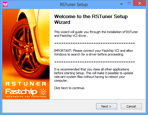
- 2.0 Installation
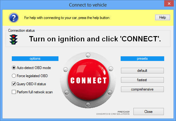
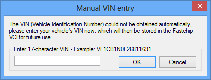
- 3.0 Connecting to the vehicle
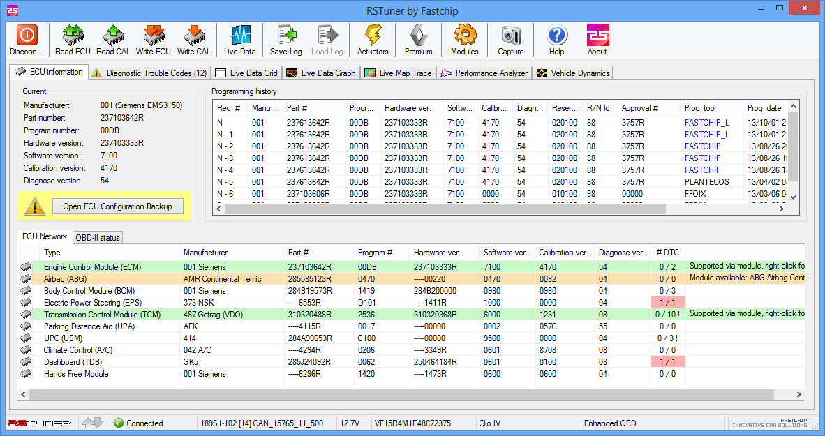
- 4.0 Using RSTuner
- 5.0 Which calibration file to use
- 6.0 Reprogramming precautions
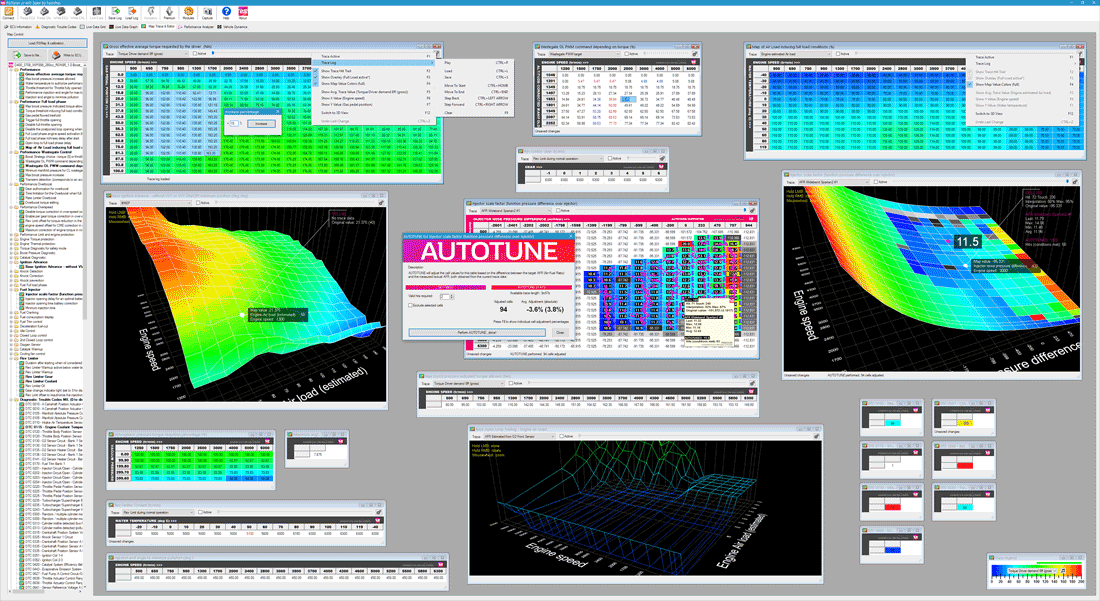
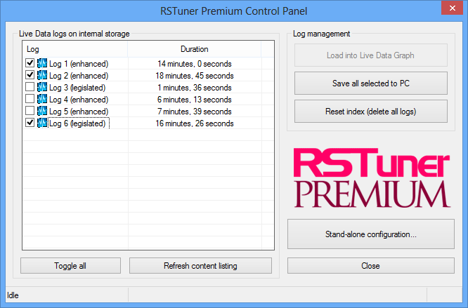
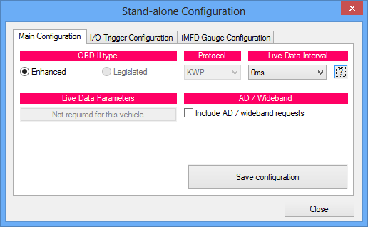
- 7.0 RSTuner Premium
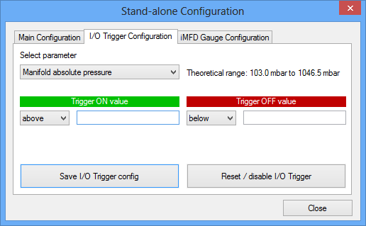
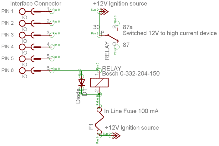
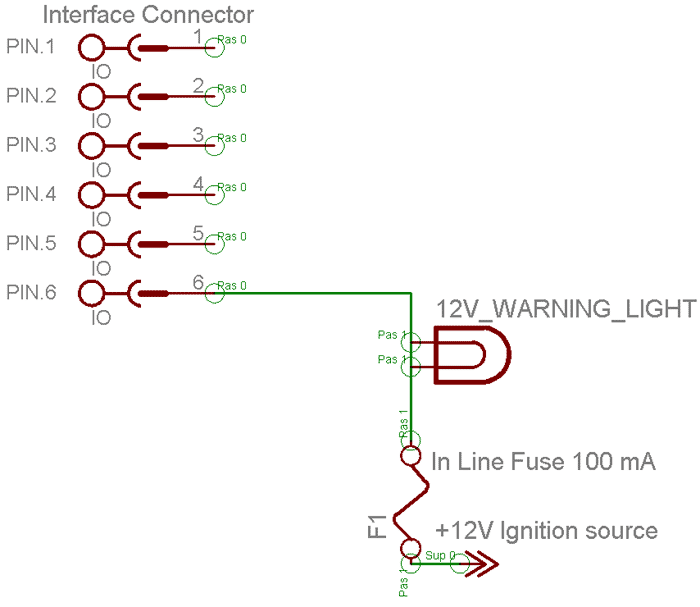
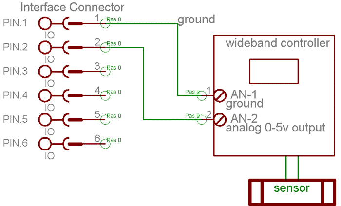
- 8.0 Input / Output (IO)
- 9.0 Supported models
- 10.0 Modules
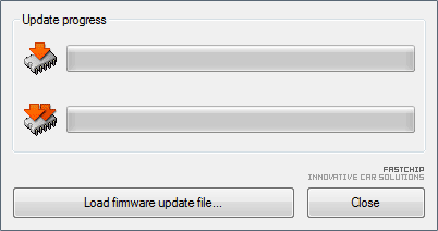
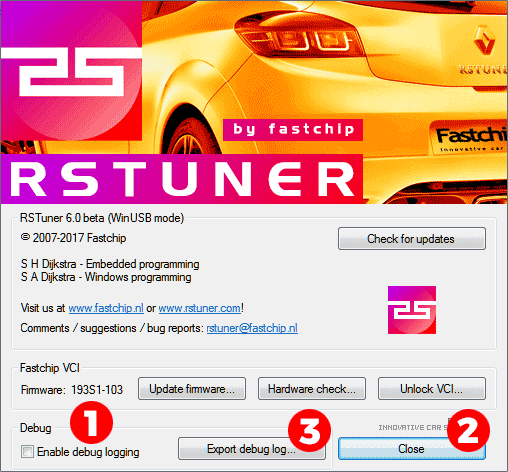
- 11.0 Firmware Update
- 12.0 Online resources
- 13.0 Disclaimer
- 14.0 Troubleshooting
- 15.0 Contact
 >
>


 .
.